Breadboards allow us to experiment with many different kinds of circuits without committing to a permanent design. Since we can connect various components without soldering anything, we can reuse everything when we are finished with one idea and ready to try another. In this way, a breadboard lets us tinker with electronics projects, treating the components like lego pieces.
There are many types of breadboards, with different shapes and sizes. Usually, there are many holes (or “points”) which are connected in different ways under the surface, allowing us to plug in components to form a circuit. A typical “full size” breadboard has 830 points, and the holes are spaced 1/10th of an inch apart (2.54 mm). Others may have a different number of holes, or a different design, but we can focus on this common layout to understand the basics.
Breadboard Layout
The 830-point breadboard has 4 “strips”: 2 “bus strips” on the outside (usually marked with blue and red lines), and 2 “terminal strips” in the center, separated by a small gap. Sometimes the rows and columns of the terminal strips are labeled with letters and numbers. There are 63 rows in each strip, with 5 points each: 2 * 5 * 63 = 630. The bus strips have 10 groups of 10 points each (separated by small spaces): 2 * 10 * 10 = 200. This totals 830 (630 + 200).
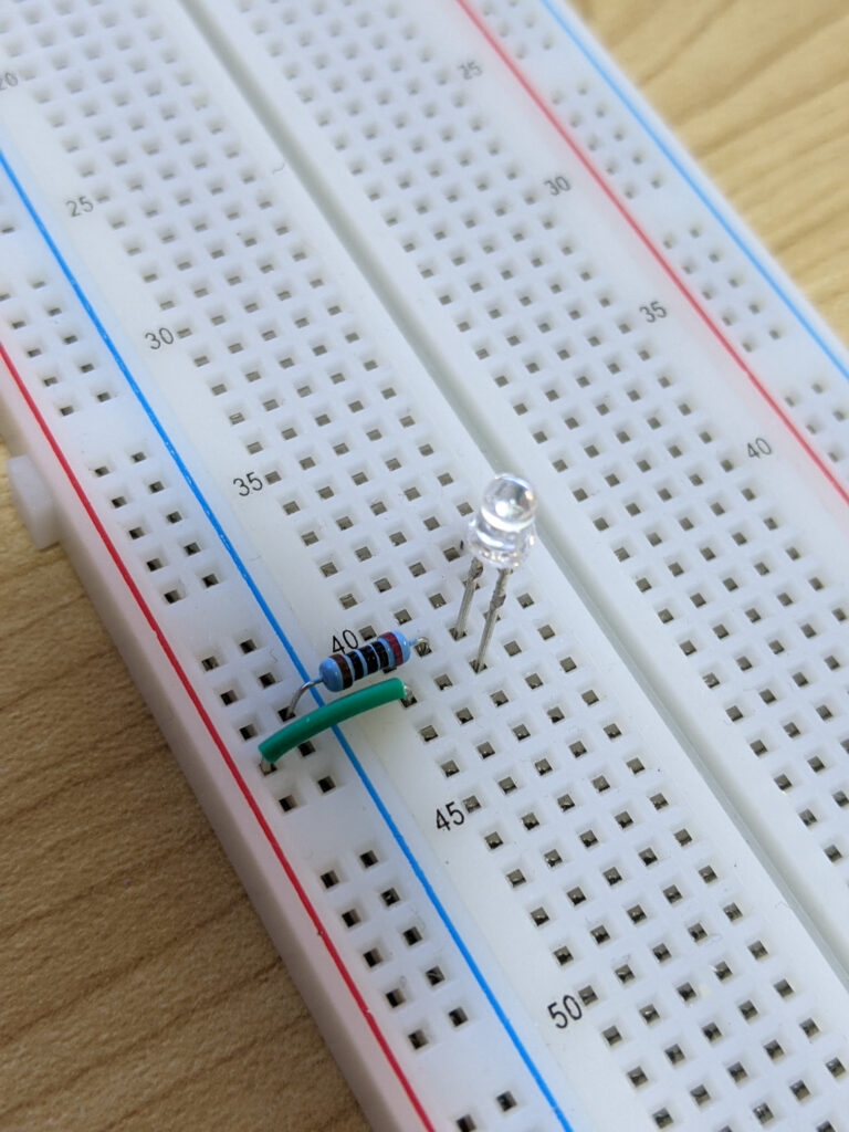
Breadboard Connections
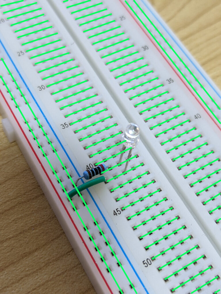
All the points in the bus strips are connected in a “column-oriented” way. This means anything plugged into the points in the same vertical column will be electrically connected. These strips are sometimes called the power rails, since they are typically connected to a power supply with the positive terminal connected to the column marked red, and the negative terminal connected to the column marked blue.
In the terminal strips, each row of 5 points is connected horizonally. This means if we connect a pin (the leg of a component) to a point in a row, the other 4 points are available to make a connection with other components.